Showing posts with label 6. Show all posts

Friday, October 31, 2014

6 to 15V DC to DC Converter

A very efficient 6V to 15V DC to DC converter using LM2585 is shown here. LM2585 is a monolithic integrated voltage converter IC that can be used in various applications like flyback converters, boost converters, forward converters, multiple output converters etc. The circuit requires minimum number of external components and the IC can source up to 3A output current.

 
6 to 15V DC to DC Converter Circuit diagram :


dc-to-dc-converter-Circuit
6 to 15V DC to DC Converter Circuit Diagram

Here the IC is wired as a boost converter where resistors R1 and R2 are used to set the output voltage .The junction of R1 and R2 is connected to the feedback pin of IC1. Capacitor C4 is the input filter while capacitor C1 the filter for output. Network comprising of resistor R1 and capacitor C2 is meant for frequency compensation. Inductor L1 stores the energy for acquiring boost conversion.
Notes:    
  • Assemble the circuit on a good quality PCB.
  • LM2585 requires a heatsink.
  • Output voltage is according to the equation Vout =( (R1/R2)+1) x 1.23.
  • Capacitors other than C4 and C1 are ceramic capacitors.
  • Maximum output current LM2585 can source is 3A. 

Source : Circuitstoday

Monday, October 27, 2014

TA8256BH bassed 6 watts 3 channel audio amplifier Diagram Circuit


Using the TA8256BH audio amplifier IC can be designed a very simple 3 channel audio power amplifier for audio applications that require a small power .
This IC provides an output power of 6 watts per channel (at VCC = 20 V, f = 1 kHz, THD = 10%, RL = 8 Ω).

TA8256BH audio amplifier project is suitable for power amplifier of TV and home Stereo.
Some important build in functions of these audio circuit project , based on the TA8256BH are : audio muting circuit , thermal shut down protection circuit, over voltage protection circuit .
TA8256BH power amplifier can operate over a wide range input voltage from 10 to 30 volts .

Monday, September 8, 2014

6 12 Volt Adjustable Power Supply Circuit

adsjust
Power Supply in this article use a regulator that is composed of 2 pieces of NPN transistor. A transistor acts as a power regulator and a transistor again serves as a controller output voltage.

Read more

Friday, September 5, 2014

6 8A 0 28V Variable Power Supply Circuit

6-8A

This is the schematic diagram of variable power supply. The output voltage of this power supply schema can be adjust from 0V to 28V DC, while the current output is static the rang is about 6A up to 8A.

Parts List:
R1 = 2K2 Ohm 2,5 Watt
R2 = 240 Ohm
R3,R4 = 0.1 Ohm 10 Watt
R7 = 6K8 Ohm
R8 = 10K Ohm
R9 = 47 Ohm 0.5 Watt
R10 = 8K2 Ohm
C1, C7, C9 = 47nF
C2 = 4700uF/50v – 6800uF/50v
C3, C5 = 10uF/50v
C4, C6 = 100nF
C8 = 330uF/50v
C10 = 1uF/16v
C11 = 22nF
D1…D4 = four MR750 diodes (MR750 = 6 Ampere diode) or 2 x 4 1N5401 diodes.
D5 = 1N4148, 1N4448, 1N4151
D6 = 1N4001
D10 = 1N5401
D11 = LED
D7, D8, D9 = 1N4001
TR = 2 x 15 volt (30volt total) 6+- Ampere
IC1 = LM317
T1, T2 = 2N3055
P1 = 5k
P2 = 47 Ohm or 220 Ohm 1 Watt
P3 = 10k trimmer pot
F1 = 1 Amp
F2 = 10 amp


Source: schemadiagram.net

Monday, September 1, 2014

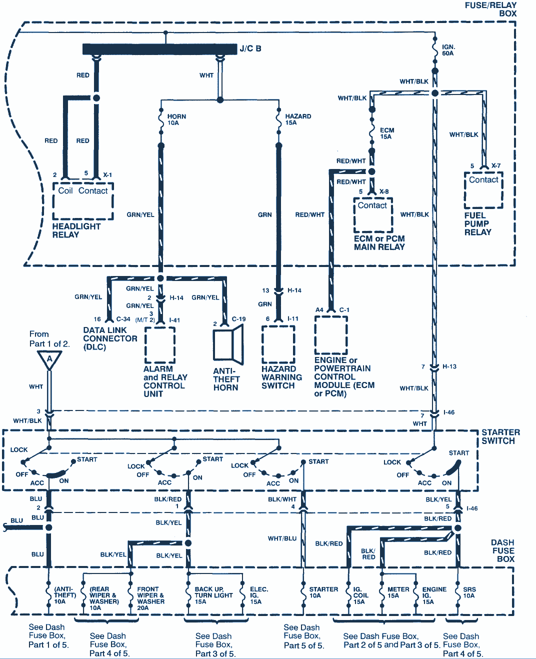
1998 Isuzu Rodeo 3 2 6 cyl Wiring Diagram

1998 Isuzu Rodeo 3.2 6 cyl Wiring Diagram


This is 1998 Isuzu Rodeo 3.2 6 cyl Wiring Diagram: red wire, coil contact, headlight relay,
connector, relay ctrl, fuse box, rear wipper, starter, theft horn, black wire, horn, hazard