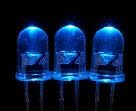
This is LED flashing schema Here I have used common IC LM3909.This schema operates with 3V power supply.After making two diagram like this you can build a multi vibrator schema.
This is simple Bridge Circuit Diagram With One Power Supply. For systems with only one power supply, two op amps act as instrumentation and buffer amps. The OPA111 AM buffers the reference mode of the bridge and applies that voltage to the instrumentation amps ref terminal. Output is taken between the amplifier outputs to exclude the fixed output offset.
The additional op amp creates a bridge error of 2, where IB=bias current of op amp and R is the resistance of one leg of the bridge.