Showing posts with label solar. Show all posts

Saturday, September 13, 2014

Pump Controller For Solar Hot Water System

This schema optimises the operation of a solar hot water system. When the water in the solar collector is hotter than the storage tank, the pump runs. The schema comprises two LM335Z temperature sensors, a comparator and Mosfet. Sensor 1 connects to the solar collector panel while Sensor 2 connects to the hot water panel. Each sensor includes a trimpot to allow adjustment of the output level. In practice, VR1 and VR2 are adjusted so that both Sensor 1 and Sensor 2 have the same output voltage when they are at the same temperature. The Sensor outputs are monitored using comparator IC1.

When Sensor 1 produces a higher voltage than Sensor 2, which means that sensor 1 is at a higher temperature, pin 1 of IC1 goes high and drives the gate of Mosfet Q1. This in turn drives the pump motor. IC1 includes hysteresis so that the output does not oscillate when both sensors are producing a similar voltage. Hysteresis comprises the 1MO feedback resistor between output pin 1 and non-inverting input pin 3 and the input 1kO resistor. This provides a nominal 12mV hysteresis so that voltage at Sensor 1 or Sensor 2 must differ by 12mV for changes in the comparator output to occur.


pump-controller-for-solar-hot
Pump Controller For Solar Hot Water System

Since the outputs of Sensor 1 and Sensor 2 change by about 10mV/°C, we could say that there is a degree of hysteresis in the comparator. Note that IC1 is a dual comparator with the second unit unused. Its inputs are tied to ground and pin 2 of IC1 respectively. This sets the pin 7 output high. Since the output is an open collector, it will be at a high impedance. Mosfet Q1 is rated at 60A and 60V and is suitable for driving inductive loads due to its avalanche suppression capability. This clamps any inductively induced voltages exceeding the voltage rating of the Mosfet.

The sensors are adjusted initially with both measuring the same temperature. This can be done at room temperature; adjust the trimpots so that the voltage between ground and the positive terminal reads the same for both sensors. If you wish, the sensors can be set to 10mV/°C change with the output referred to the Kelvin scale which is 273K at 0°C. So at 25°C, the sensor output should be set to (273 + 25 = 298) x 10mV or 2.98V.

Note:
The sensors will produce incorrect outputs if their leads are exposed to moisture and they should be protected with some neutral cure silicone sealant. The sensors can be mounted by clamping them directly to the outside surface of the solar collector and on an uninsulated section of the storage tank. The thermostat housing is usually a good position on the storage tank.

Saturday, September 6, 2014

Controller of Solar charger Wiring diagram Schematic

 This is the simple Controller of Solar charger Circuit Diagram .When connecting a solar panel to a rechargeable battery, it is usually necessary to use a charge controller schema to prevent the battery from overcharging. Charge control can be performed with a number of different schema types. Lower power solar systems can use a series analog charge controller. Series regulators control the charging current by interrupting the flow of current from the solar panel to the battery when the battery reaches a preset full voltage. MPPT controllers use an inductor for energy storage and a high frequency switching schema to transfer the energy to the battery.

This schema is for a shunt-mode charge controller. In a shunt-mode schema, the solar panel is permanently connected to the battery via a series diode. When the solar panel charges the battery up to the desired full voltage, the shunt schema connects a resistive load across the battery to absorb the excess power from the solar panel. The main advantage of shunt-mode solar regulation is the lack of a switching transistor in the power path between the solar panel and battery. Switching transistors are non-perfect devices, they waste a percentage of available solar power as heat. Inefficiency in the shunt-mode controller’s switching transistor does not effect charging efficiency, it only turns on when excess power is purposely being wasted.

Controller of Solar charger Circuit Diagram 


Solar power is routed from the PV panel through the 1N5818 Schottky diode to the battery. When the battery reaches the full setpoint, the output on the lower half of the TLC2272 dual op-amp turns on. This activates the IRFD110 MOSFET transistor and connects the 68 ohm 3W load resistor to the battery. The load across the battery causes the battery voltage to drop, and the comparator schema turns back off. This oscillation continues while solar power is available. The 300nF capacitor across the op-amp slows the oscillation frequency down to a few hertz. The two 100K resistors in series provide a regulated 4.5V reference point for use as comparator reference points.

The 2N3906 transistor is wired with a zener diode in its base schema, when the PV voltage is above 12V, the 2N3906 transistor turns on and enables the comparator schema. The upper half of the TLC2272 op-amp inverts the dump load control signal, this is used to power the high intensity red LED. The LED turns on when the battery reaches the full setpoint. The LED does not waste any useful charging power since it only turns on when the battery is full.

The 78L09 IC provides 9V regulated power to the comparator schemary. Operational power for this schema is provided entirely from the PV panel, there is virtually no power taken from the battery at night.

This schema can be modified for higher amperage by replacing the 1N5818 diode, 68 ohm load resistor and IRFD110 MOSFET with higher power components. If the load resistor is connected directly across the PV panel at noon on a sunny day, the PV output voltage should drop to 12V or less. Higher power PV panels will require a resistor with lower ohms and a higher wattage rating. In cold climates, it may be useful to use the load resistor’s heat to keep the battery warm.

Operation of a high power version of this schema with a wind generator should be possible, although the author has not tried this. For a 20 amp version of this schema, the IRFD110 MOSFET should be replaced with an IRFZ44N and the 1N5818 schottky diode should be replaced with a 20L15T. Both of these parts should have large heat sinks. The 68 ohm/3W resistor should be changed to a much larger resistor, An 0.6 ohm/250W resistor would be able to handle 20 amps at 12V.

Monday, September 1, 2014

Solar Panel Lead Acid Batteries Charger


Solar Panel Lead-Acid Batteries Charger Schematic


This Batteries Charger is advised for charging closed lead-acid batteries with a solar console in baby and carriageable applications. The accepted diode that prevents the array from absolution through the solar console has been replaced by a FET-comparator combination.

The batteries charger will stop charging already a pre-set voltage (temperature compensated) has been reached, and recommence charging aback the voltage has alone off sufficiently. The amount is broken aback the array voltage drops beneath 11V and reconnected aback it gets aback to 12.5V.

The batteries charger ambit has the afterward features:

* Charges until Vbat = 13.8V (adjustable), again float charges;

* Shuts bottomward amount aback Vbat <11v (adjustable), resets at 12.5v;

* Temperature compensation;

* Will assignment with bargain and readily accessible apparatus like LM393 comparators and BUZ11 FETs;

* Uses beneath than 0.5mA aback application TLC393 comparators;

* Burns beneath than 20mW in FETs aback charging at 0,5A. (More big-ticket FETs with a lower RDSON will crop alike bigger results). Note that the charging accepted is bound alone by the solar console used.

Thursday, August 28, 2014

Parallel Connecting Solar Panels


Parallel Connecting Solar Panels

Monday, August 25, 2014

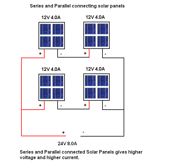
Series Parallel Connecting Solar Panels

Series Parallel Connecting Solar Panels

Sunday, August 24, 2014

Lighting Garden with Solar Energy Wiring diagram Schematic

This is an economic schema of a mini solar lighting system, solar panel 6V/2W is used to charge a rechargeable 4V/800mAh through a current limiting schema load that uses a LM317T adjustable regulator 3 pin (IC1). Assuming a sunny day 6 hours, a panel will enviarr 2 watts for approximately 900mAh battery. The current can be reduced by increasing the value of R1, for example, 8.2 to 10 ohms ohms.

 Lighting Garden with Solar Energy Circuit Diagram

Lighting


Specification of a typical solar panel 

6V/2W:Maximum power (Pm): 
2WWorking Voltage (Vmp): 
9VWorking Current (Imp): 
220mAOpen Circuit Voltage (Voc): 
10.5VPower Tolerance: -3% to 5%

Thursday, August 21, 2014

Simple Hybrid Solar Charger Wiring diagram Schematic

In the electronic world D. Mohankumar is the most famous name his creations are very importent every time. Efficiency of a solar charging system depends on the weather conditions. Usually the solar panel gets four to five hours of bright sunlight in a day. If the weather is cloudy or rainy, it affects the charging process and the battery does not attain full charge. This simple hybrid solar charger can solve the problem as it can charge the battery using both solar power as well as AC mains supply. When output from the solar panel is above 12 volts, the battery charges using the solar power. When the output drops below 12 volts, the battery charges through AC mains supply. Fig. 1 shows the author’s prototype. 

Fig.
 Fig. 1: Author’s prototype

Circuit and working
Fig. 2 shows schema for the hybrid solar charger, which is built around a 12V, 10W solar panel (connected at SP1), operational amplifier CA3130 (IC1), transistor BC547 (T1), 12V single-changeover relay (RL1), step-down transformer X1 and a few other components.


Simple

Fig. 2: Hybrid solar charger schema diagram


In bright sunlight, the 12V, 10W solar panel provides up to 17 volts DC with 0.6-ampere current. Diode D1 provides reverse polarity protection and capacitor C1 buffers voltage from the solar panel. IC1 is used as a simple voltage comparator. Zener diode ZD1 provides a reference voltage of 11 volts to the inverting input of IC1, while the IC’s non-inverting input gets voltage from the solar panel through R1.

Working of the schema is simple. When output from the solar panel is 12 volts or more, zener diode ZD1 conducts and provides 11 volts to the inverting terminal of IC1. Since its non-inverting input gets a higher voltage at this time, the output of the comparator turns high and the same is indicated by glowing green LED1. Transistor T1 then conducts and relay RL1 energizes. Thus the battery gets charging current from the solar panel through the normally-open (N/O) and common contacts of relay RL1.


LED2 indicates charging of the battery. Capacitor C3 is provided for clean switching of transistor T1. Diode D2 protects T1 from back EMF and diode D3 prevents the discharge of battery current into the schema.

When output from the solar panel drops below 12 volts, output of the comparator turns low and the relay de-energizes. Now the battery gets charging current from the transformer-based power supply through the normally-closed (N/C) and common contacts of the relay. This power supply comprises step-down transformer X1, rectifying diodes D4 and D5, and smoothing capacitor C4.

Fig.
 Fig. 3: An actual-size, single-side PCB for the hybrid solar charger

Fig.
Fig. 4: Component layout for the PCB

Construction and testing
An actual-size, single-side PCB for the hybrid solar charger is shown in Fig. 3 and its component layout in Fig. 4. After assembling the schema on PCB, enclose it in a suitable box. Use high-gauge (thick) wires to connect the solar panel and the battery to the schema.

To test the schema for proper functioning, remove the solar panel from connector SP1 and connect a DC variable voltage source. Set some voltage below 12V and slowly increase it. As the voltage reaches 12V and goes beyond, the logic at test point TP2 changes from low to high. The transformer-based power supply voltage can be checked at test point TP3.


Sourced By: EFY Author : D.Mohnkumar