Sunday, November 2, 2014

RESISTOR TO REDUCE L200 POWER DISSIPATION ELECTRONIC DIAGRAM

RESISTOR TO REDUCE L200 POWER DISSIPATION ELECTRONIC DIAGRAM

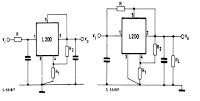
Instead of in series with the input, the resistor R can be connected between pins 1 and 2 of the IC if the load is constant. You can see this in the right figure. This will make some part of the load current flows through the resistor and the other part through the device.
Related Posts:

  • Simple UPS Power SupplyThis circuit is a simple form of the commercial UPS, the circuit provides a constant regulated 5 Volt output and an unregulated 12 Volt supply. In the event of electrical supply line failure the battery takes over, with no sp… Read More
  • Power High Performance UPS With 8A Switcher CircuitPower High Performance UPS With 8A Switcher CircuitAll high-current switchers are sensitive to board layout; take care when designing the pc board. Youll obtain the best results by using a multilayer board, so you can dedicat… Read More
  • Fuse Box BMW 1992 325i Power Distribution DiagramFuse Box BMW 1992 325i Power Distribution Diagram - Here are new post for Fuse Box BMW 1992 325i Power Distribution Diagram.Fuse Box BMW 1992 325i Power Distribution Diagram Fuse Panel Layout Diagram Parts: normal speed rela… Read More
  • Schematic Audio Power Amplifier with IC TDA2822TDA2822 is manufactered by PHILIPS , its based on this amplifier . Minimum voltage 3 volts and maximum voltage 15 volts. Power output 2 x 1,8 stereo with 4 Ohm impedance. Quiescent current 6 mA , sensitive input is 30 Hz to 1… Read More
  • Overcurrent Trip Regulator Power SupplyOvercurrent Trip Regulator Power Supply CircuitAvailable to 4QD-TEC members are rather more sophisticated power supplies: a larger supply of the same nature s this is available, with parts information and board layout. A Circ… Read More

0 comments:

Post a Comment

Note: Only a member of this blog may post a comment.